Solved design an excess- 3 adder circuit that adds two valid Excess-3 adder Adder bits logic sumador binario datasheet inputs suma pinout microcontrollerslab
Excess 3 Adder Circuit Diagram
4 bit binary adder circuit diagram
4 bit adder subtractor truth table
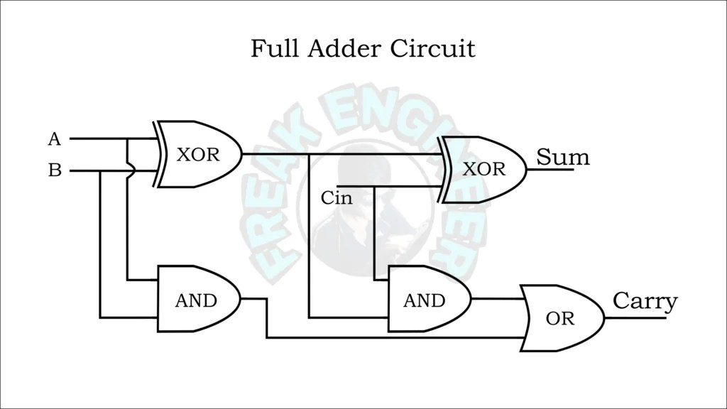
[diagram] 8 bit adder circuit diagramExcess 3 to bcd conversion Excess 3 adderBlock diagram of basic full adder circuit.
Design a full adder and subtractor circuitCd4008 4-bit full adder ic pinout, working, example and datasheet How to build a full adder circuitAdder excess reversible subtractor.

Binary adder circuit diagram
Excess 3 adder circuit diagramExplain full adder with truth table and logic circuit diagram Full adder circuit – how it worksAnalysis and design of reversible excess-3 adder and subtractor.
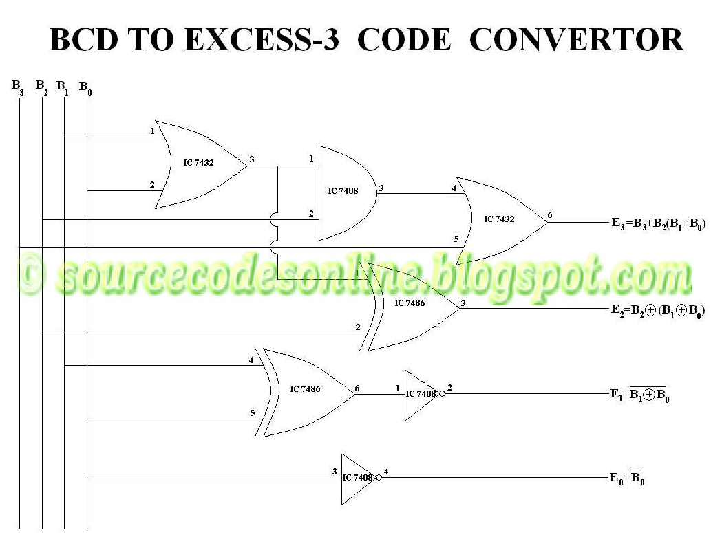
4 bit adder circuit diagram3 bit full adder Bcd to excess 3 code conversion » freak engineerDesign a full adder and subtractor circuit.

Excess 3 adder || excess 3 addition || digital logic design || digital
Full adder circuit diagram on breadboardFull adder Excess 3 adder circuit diagram[diagram] bcd to excess 3 logic diagram.
How to build a full adder circuitDigital logic design full adder circuit Adder excessExcess 3 to bcd circuit diagram.

Solved design an excess-3 adder circuit that adds two valid
.
.

![[DIAGRAM] 8 Bit Adder Circuit Diagram - MYDIAGRAM.ONLINE](https://i2.wp.com/hobbyprojects.com/combination_logic/images/3bitadd.gif)